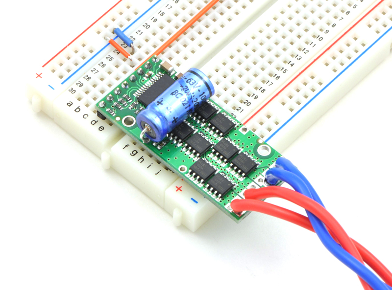
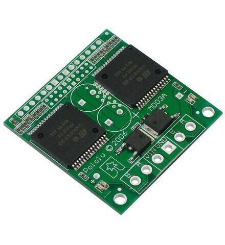
The driver’s default configuration uses six GPIO pins to control the motor drivers, making use of the Raspberry Pi’s hardware PWM outputs, and it uses two additional pins to read status outputs from the drivers. Driver Information. Compatibility: Windows 7 or Later. Where to Download? Click the link below to download. Pololu Socket to External Drivers converter board. It plugs into a Pololu stepper driver socket and re-routs the Step,Direction,Enable,Ground pins to the stepper motor ports connector. Forum discussion on external drivers for the Raspberry Pi CNC Hat: Using Pololu sockets for external stepper drivers.
Arduino library for the Pololu Dual VNH5019 Motor Driver Shield C MIT 73 42 1 1 Updated Dec 17, 2020.
Release status: working
| Description | Stepper driver for RAMPS, Sanguinololu, Gen7 |
| License | |
| Author | |
| Contributors | |
| Based-on | |
| Categories | |
| CAD Models | |
| External Link |
- Please note: Pololu stepper driver boards has 0.05 ohm sense resistors instead of StepStick 0.2 ohm.
A Pololu stepper driver board is a well known RepRap machinestepper motor driver.
The Pololu stepper driver boards are made as pluggable modules to a electronics motherboard. A good reason of this design is, that it is easy to exchange the Pololu boards when troubleshooting - or when a board has burned out.
- 1List of Boards
- 2Tuning motor current
List of Boards
Pololu driver boards (8+8 pins):
- Pololu A4988 stepper driver - A4988-based; equivalent to A4983-board but offers overcurrent protection. If the boards get too hot, they will interrupt the current until it cools a bit. If the current is too high for the heat sinking, the motors will pulse as the current is interrupted and restored. See http://forums.reprap.org/read.php?4,116813,116832,quote=1 and its video. Try reducing the current until the pulsing stops.
- Pololu A4983 stepper driver - A4983-based; (discontinued).
Pololu driver boards with Voltage Regulators (longer boards - 8+14 pins):
- Pololu A4988 Stepper Motor Driver Carrier with Voltage Regulators - A4988-based; equivalent to A4983-board but offers overcurrent protection.
- Pololu A4983 Stepper Motor Driver Carrier with Voltage Regulators - A4983-based; (discontinued).
As user Nophead has pointed out, that Pololu driver is a nice design, but with one big shortcoming: it will run hot, and is difficult to cool because it's so small. So what I've done is to design the electronics in such a way that they both perform their function and act as a physical duct for the flow from a fan to direct their own cooling. A happy side-effect of this is that the resulting PCBs are very simple, and can be made single-sided without any thin tracks. That is is why RepRap itself can make them. We must walk before we can run.. an another way to improve heat dissipation is the use of small heat sink, unfortunately the small adhesive pad are not so adhesive.. so the use of some thermal conductive glue make the thing easier (like this one, in french www.pc-look.com/boutik/63648.html but if you google: Arctic Silver - Arctic Alumina™ Thermal Adhesive you will find it or equivalent)
Alternatives
- SureStepr SD82B - http://www.panucatt.com/product_p/sd82b.htm
- DRV8825 Stepper driver (1.5 A max w/o heatsink! 2.2 with) - http://www.pololu.com/catalog/product/2132
Drivers Policy Safety Manual
Tuning motor current
A4988 and similar
Per the A4988 datasheet, the calculation for the maximum trip current is:
With Pololus, the sensing resistors are Rs=0.05 ohm, so a Vref of 0.4 should produce a maximum current of 0.4/(8*0.05)=1A. Clockwise increases the current which will make the motor run hotter and counterclockwise reduces it which will cool it down (see forum thread 159081).

As another example, aiming for 50% temperature rise on 1A rated steppers by using max 0.7A, so rearrange it as:
or
With a measured Vref of 0.273V, I should expect 0.6825A, and I measured the current through one coil as 0.486A in full step mode, which should be 0.7071 of the full trip current, or I_TripMax= 0.486/0.7071= 0.687A, which seems close enough.
The Vref signal is accessible as the 'VREF' pin on the carriers with voltage regulators, as the through-hole via on the carriers without, and also as the wiper on the trim pot itself on both carriers.
Note 1: for StepStick, the Rs=0.2 ohm, so you'd get 4 times the Vref at the same current.
Note 2: most 'Made in China' A4988 Pololu knock-offs have Rs=0.1 ohm.
DRV8825
For the Pololu DRV8825 Stepper Motor Driver, the current sense resistors are 0.1Ω. The calculation changes to 'I_TripMax = Vref × 2', or 'Vref = I_TripMax / 2'.
Note: Check pinout before placing driver, Vref pot on the Pololu DRV8825 is usually on the opposite side of the board when compared to the Pololu A4988, placing driver backwards can destroy the driver.
As an example, running at 70% of a maximum 1A motor current, use the formula as follows:
The maths in full
For repraps, logic supply voltage (VDD) is 5V. For Pololu driver boards, the trimpot is 100kohm, R5 resistor is 20kohm, sense resistors R7 and R8 are 0.05ohm
VREF max = (TrimpotMaxR/(TrimpotMaXR+R5)) x VDD = (100,000 / (100,000 + 20,000)) * 5 = 4.16V
ITripMAX (effectively max motor current) = VREF / ( 8 x Sense_resistor) = 4.16 / ( 8 * 0.05 ) = 10.4A
To calculate amps from measured VREF: A = VREF / 0.4
To calculate VREF required for a target current: VREF = A * 0.4
Heat Consideration
The way the IC is designed, it wicks heat much better through the large pad on the underside than it does through the outside of the packaging. This means the heatsink is not actually in the ideal place to wick heat away, and the quality of the solder job underneath is extra important. On some chinese knockoffs (white board and the pot has no built in stop) I notice they overheat and go into thermal shut down before a real pololu board would, even with a heat sink and fan. Heat dissipation could possibly be improved by re-flowing the solder on a hot plate, but I have not tried this as they are my backups.Pololu also offers a 'black Edition' board which has extra copper and multiple layers in the PCB to help wick heat away from the IC and keep it cool. This is said to add on an extra 0.2 amps that can be maintained without heat sinking. Also using the same logic, it is more effective to blow cooling air under the board rather than over it, and brilliant design work on the RAMPS boards allows this quite easily.
Upgrades
The voltage divider and pot are poorly selected for the currents used. The board uses a 10k pot and 20k resistor to set the vref, so the effective range is 0-1.7 volts, or 0-4.2 amps! The IC is only rated for a maximum of two amps if you have perfect heat dissipation. This makes it much more difficult to set the ref voltage since at 1/4 turn you have maxed out your driver. The resistor is the easiest to change. You simply need to swap it with one rated at 51K ohms. (part number below) With this modification, the max current is 2.05 A with vRef = 0.82V.
Any resistor in a 0603 SMD package will work. Resistors with a higher resistance will lower the maximum current even further. Some have reported using a 68K-ohm resistor which brings the maximum current down to 1.6 amps. Many of the Pololu clones will shut down before producing this much current, even when cooled with a heatsink and fan, so a slightly higher resistance would work as well.
51K-ohm DigiKey.com part number: 311-51KGRCT-ND
Double check the sense resistor values before making this upgrade, if you actually have stepsticks with 0.2ohm resistors, this is not needed.
See also
If you are using Windows XP, you will need to have Service Pack 3 installed before installing the drivers for the Maestro. See below for details.
Before you connect your Maestro to a computer running Microsoft Windows, you should install its drivers: Npg driver download for windows 10 pro.


- Download the Maestro Servo Controller Windows Drivers and Software (5MB zip)
- Open the ZIP archive and run setup.exe. The installer will guide you through the steps required to install the Maestro Control Center, the Maestro command-line utility (UscCmd), and the Maestro drivers on your computer. If the installer fails, you might have to extract all the files to a temporary directory, right click setup.exe, and select “Run as administrator”.
- During the installation, Windows will ask you if you want to install the drivers. Click “Install” (Windows Vista, Windows 7, and later) or “Continue Anyway” (Windows XP).
- After the installation is finished, your start menu should have a shortcut to the Maestro Control Center (in the Pololu folder). This is a Windows application that allows you to configure, control, debug, and get real-time feedback from the Maestro. There will also be a command-line utility called UscCmd which you can run at a Command Prompt.
Windows 10, Windows 8, Windows 7, and Windows Vista users: After following the steps above, you can connect a Maestro to your computer, and your computer should automatically install the necessary drivers. No further action from you is required.
Windows XP users: After following the steps above, follow steps 5 through 9 below for each new Maestro you connect to your computer.
- Connect the device to your computer’s USB port. The Maestro shows up as three devices in one so your XP computer will detect all three of those new devices and display the “Found New Hardware Wizard” three times. Each time the “Found New Hardware Wizard” pops up, follow steps 6-9.
- When the “Found New Hardware Wizard” is displayed, select “No, not this time” and click “Next”.
- On the second screen of the “Found New Hardware Wizard”, select “Install the software automatically” and click “Next”.
- Windows XP will warn you again that the driver has not been tested by Microsoft and recommend that you stop the installation. Click “Continue Anyway”.
- When you have finished the “Found New Hardware Wizard”, click “Finish”. After that, another wizard will pop up. You will see a total of three wizards when plugging in the Maestro. Follow steps 6-9 for each wizard.
After installing the drivers and plugging the Maestro in via USB, if you go to your computer’s Device Manager, you should see three entries for the Maestro that look like what is shown below:
Windows 7 device manager showing the Micro Maestro 6-channel USB servo controller. |
|---|
Windows XP device manager showing the Micro Maestro 6-channel USB servo controller. |
|---|
COM ports
After installing the drivers, if you go to your computer’s Device Manager and expand the “Ports (COM & LPT)” list, you should see two COM ports for the Maestro: the Command Port and the TTL Port. In parentheses after these names, you will see the name of the port (e.g. “COM5” or “COM6”).
You might see that the COM ports are named “USB Serial Device” in the Device Manager instead of having descriptive names. This can happen if you are using Windows 10 or later and you plugged the Maestro into your computer before installing our drivers for it. In that case, Windows will set up your Maestro using the default Windows serial driver (usbser.inf), and it will display “USB Serial Device” as the name for each port. The ports will be usable, but it will be hard to distinguish the ports from each other because of the generic name shown in the Device Manager. We recommend fixing the names in the Device Manager by right-clicking on each “USB Serial Device” entry, selecting “Update Driver Software…”, and then selecting “Search automatically for updated driver software”. Windows should find the Maestro drivers you already installed, which contain the correct name for the port.
Drivers Policy Template
If you want to change the COM port number assigned to your USB device, you can do so using the Device Manager. Bring up the properties dialog for the COM port and click the “Advanced…” button in the “Port Settings” tab. From this dialog you can change the COM port assigned to your device.
If you use Windows XP and experience problems installing or using the serial port drivers, the cause of your problems might be a bug in older versions of Microsoft’s usb-to-serial driver usbser.sys. Versions of this driver prior to version 5.1.2600.2930 will not work with the Maestro. You can check what version of this driver you have by looking in the “Details” tab of the “Properties” window for usbser.sys in C:WindowsSystem32drivers. To get the fixed version of the driver, you will need to install Service Pack 3. If you do not want Service Pack 3, you can try installing Hotfix KB918365 instead, but some users have had problems with the hotfix that were resolved by upgrading to Service Pack 3. The configuration software will work even if the serial port drivers are not installed properly.
Native USB interface

There should be an entry for the Maestro in the “Pololu USB Devices” category of the Device Manager. This represents the Maestro’s native USB interface, and it is used by our configuration software.
Driver Pololu 8825
Related products
Drivers Policy Manual
| Micro Maestro 6-Channel USB Servo Controller (Partial Kit) |
| Micro Maestro 6-Channel USB Servo Controller (Assembled) |
| Mini Maestro 12-Channel USB Servo Controller (Assembled) |
| Mini Maestro 12-Channel USB Servo Controller (Partial Kit) |
| Mini Maestro 18-Channel USB Servo Controller (Assembled) |
| Mini Maestro 18-Channel USB Servo Controller (Partial Kit) |
| Mini Maestro 24-Channel USB Servo Controller (Assembled) |
| Mini Maestro 24-Channel USB Servo Controller (Partial Kit) |

