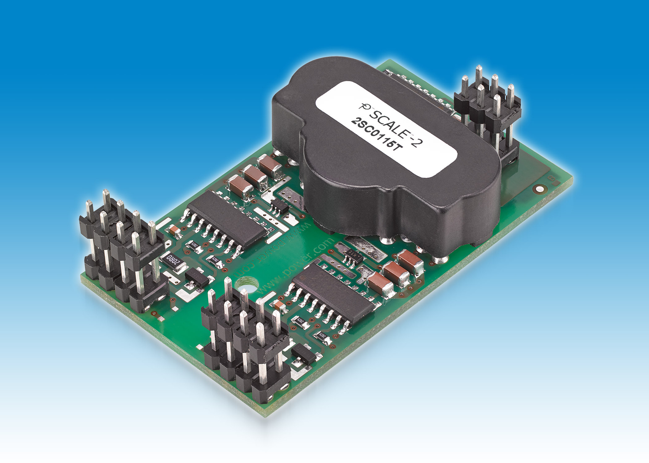
Introduction: OPTO-MOSFET Driver
- Download Opto Driver App
- Download Opto Driver Download
- Download Opto Drivers
- Download Opto Driver Installer
Opto-Driver Output Short-Circuit Current VIN = 30V, FB = 1.5V, COMP = SS = Open, OPTO = 0V (Note 6) l 10.5 15 18 mA Opto-Driver Output Sink Current FB = 1V, OPTO = 1.2V (Note 7) l. Optos introduced ultra-widefield (UWF™) retinal imaging to enable eyecare professionals to discover, diagnose, document and treat ocular pathology that may first present in the periphery - pathology which may go undetected using traditional examination techniques and equipment.
Hi. My absolutely first enclosure to MOSFET’s. After studying ”lot’s” of them in INSTR. & Arduino & elsewere of them users having problems with controlling them mosfets with logics.
Problems there seems to be:
1. To get a proper Volt-level to the gate from logics.
2. To get a NON-inverting output to the fet
3. To NOT use the same power-rail to both logic & load
4. To have a simpel, (few components), solution to all above.
Download Opto Driver App
I rigged up my own suggestion to try to solve these problems.
Download Opto Driver Download
And voilá, it worked like charm, (my first mosfet connection ewer).
I attach here the schematics and them data of the optocoupler and the Mosfet i used. Keep in mind: My solution is just for guidelines for anyone to use. There are 100’s of different kind of optocouplers, so that’s why I don’t here go closer to the specs, same goes for the Mosfet.
The principal idea is that when the switch, (or logic), is LOW, the optocoupler LED is ON.
R1 is the LED current limitor resistance, (you need to dimension it to your own demands).
The output is now ON thus giving 0V at pin 8 to the GATE
With the switch, (or logic), is HIGH, (or no potential at all), the output at pin 8 is OFF. Ralink others driver download for windows. Now the VDD, (your ”load” voltage), to the GATE goes via R2, voilá.
The resistor R3, (optional), is there for a voltage-divider. This is if your load voltage ower-rides the volt-level to the gate allowed, (e.g. load volt > 15V).
I haven’t tested my circuit with any heawy load’s yet. Only with 20V/ 500mA. The mosfet was colder, (after 15minutes ON), that my finger, (couldn’t get any warmth at all), There’s a ton of details to concider, delays…. etc.
Download Opto Drivers
Keep in mind: this is ”just” a guide-line for that I tested of curiosity them Mosfet’s
Step 1: The Schematic Picture
There are 2 totally independent channels for them MOSFET’s,
including the Power-rails and separate fuses. Use them switches 1,2 to choose the MOSFET to be active either with a LOW or HIGH level from the logic, respectively.
Download Opto Driver Installer


Step 2: PCB Layouts
The layout is double-sided. The complete Design is in ”Gerber form” in the ZIP-file
If Windows doesn't find a new driver, you can try looking for one on the device manufacturer's website and follow their instructions. Reinstall the device driver. In the search box on the taskbar, enter device manager, then select Device Manager. Right-click (or press and hold) the name of the device, and select Uninstall. Restart your PC. Qmenr laptops & desktops driver download. Download the latest drivers, software, firmware, and diagnostics for your HP products from the official HP Support website. Driver version may differ depending on the wireless adapter installed. Driver: Windows 7, 32-bit. Windows 7, 64-bit. 21.40.5 Latest: 2/18/2020: Intel® PROSet/Wireless Software and Drivers for Windows 8.1. This download record installs Intel® PROSet/Wireless WiFi Software 21.40.5 including driver.
Attachments

- FET IRFZ44N.pdf
Step 3: Component Side Copper
Step 4: Solder Side Copper
Be the First to Share
Recommendations

Microcontroller Contest
Automation Contest
Make it Glow Contest

